Week Six
Click the Arrow to Proceed to Project Page
Click the Arrow to Proceed to Project Page
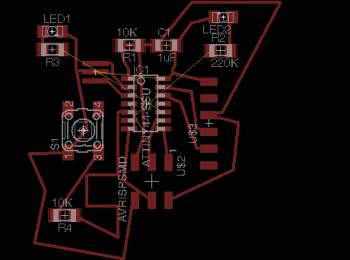
Designing spacecraft using Eagle

The process:
This week we were given the SUPER EXCITING task of creating our own circuit board using the "Echo Hello World" components on the fab site. We were told to add an LED and a button to the board. I decided to create a rocketshiPCB to give my board a bit more character.
Method:
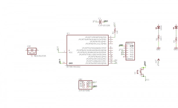
We were introduced to a couple different software options, but the general recommendation was to use Eagle, as the program is relatively usable for beginners. It essentially allows you to drag and drop elements of the circuit and ensure that components connect appropriately.
Jean-François provided us with excellent tutorials. I worked through the Sparkfun ones with Eagle and it really helped me dive into the software. Pip also has some extremely useful information on her page.
Before starting, I imported the fab library (which contains most of the necessary components) by copying it into my Eagle directory - on my computer this is under applications - and adding it to the library files. When I opened a new schematic, I hit "Use" under the Libraries Menu and selected the fab library.

SOME EAGLE TIPS:
-Add all your components by using the add button - this opens up a window to view all the libraries you have installed from where you can add parts to your schematic (add the fab and SparkFun libraries)
- GND, VCC, etc can be found in the SUPPLY1 Library
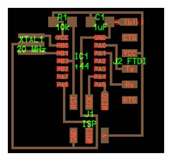
- Use small nets rather than crazy wires everywhere. Draw small net, name it, label it -> hit show to prove they are all connector: Draw a net, right click on it to name it, right click again to add a label, and draw another net at the connection point, assign it the same name. Your pieces are now connected!

- The show tool is an extremely useful way to check to see if your components are connected accurately. The bolded components in the image below are connected, as demonstrated using the show tool.
- Use the transform buttons such as move, rotate, copy and mirror to position your components on the schematic
- Many pieces are labelled (look at micro controller), so you know to connect those
- For LEDS, the order is: vcc— resistor—led—ground to ensure led does not burn out
- I think power comes in through the FTDI

Assembling the Board
Back to the key lesson from last week: NOTHING IS TRIVIAL. This process took me hours (and hours and hours). I repeatedly got to the stage at which everything would be routes....except one trace that would cross all the way through the board, rendering the connection impossible unless I wanted to short-circuit everything.
MORE EAGLE TIPS:
- Hit the switch to board tool to create a board based on your schematic. Use the group tool to move all of the components to the board, or move them piece by piece.
- Use the Ratsnest tool often to remove unecessary airwires (the yellow lines used to indicate connections) or create more efficient connections
- Make sure your design rules are up to date so that Eagle can help you account for things like min wire size, etc.: change the DRU by downloading it from the archive and loading it in the DRC menu
- Making your grid smaller can give you more control. min width for grid should be end mill size
- sometimes eagle thinks things can fit through things that they actually can’t fit through so always check routes, even if you use autoroute
-There are optimal arrangements that work best for connecting things. According to JF, rder of linking = start with micro controller, connect it to the pin header/ISP, do ground and voltage last, work component by component. I did not find this out until after I had milled my board, but I think I would do it in that order in future cases.
- When drawing the frame, place it in a separate layer, such as bottom. When exporting your final PNGs, export just the top layer (your components and traces, no labels or frame), then just the frame so that you can load them into the fab modules. Hit the monochrome button to export in black and white. CHANGE THE DPI TO 600- THIS BECAME A BIG ISSUE LATER.
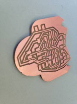
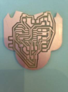
I failed at this step about a million times, so I became very familiar with the ripup tool (removes your traces), and I started over at least a dozen times. Here are some of the interesting patterns I created:
 (I almost switched to a butterfly board instead of a rocketship)

When I finally managed to connect everything, I ran the DRC to check for errors...and got 22 errors. I suspect that my highly windy circuit is not the optimal arrangement, but I ran with it, acknowledging that I would probably have to manually fix some shorts after milling.
Milling
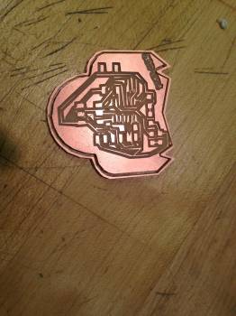
As before, I used double-stick tape to place the copper PCB board on the sacrificial layer. I made sure that the port was changed so the computer could communicate with the Modela. For the traces, I changed the tool diameter to .3. I set my x min and y min, and the result was... a mess. As shown below.

I thought maybe I had messed something up, so I tried one more time, but the result was the same.
Jonathan later told me that I had to change my image resolution to 600 dpi because the fab modules were having trouble calculating the paths. This ended up fixing the problem, but in between I tried...
VINYL CUTTING! Sadly this also failed as it was really difficult to get the blade length and force exactly correct. It either ripped the copper off of the paper or didn't cut all the way through. After three hours of playing with parameters, Juliana and I decided to go back to using the Modela. 
After changing the resolution to 600 and the tool diameter to .3, milling worked! Some traces look like they might create shorts, so I am going to use an exacto knife to fix these.
Assembly and Related Struggles
I am planning to solder all the components this morning after clearing out all the shorts on my board.
On the plus side, I suspect if I had to start over (which I will in the upcoming days), I could probably design a much more effective circuit and do so much more efficiently. I'm going to try to create a less loopy circuit, and give my rocket two LEDs instead of one! Then I'll try to program it and see how that goes...
Thanks to Jeff/Jean-François for being extremely patient and extremely helpful and looking over numerous versions of awfully designed circuits for me. Thanks to Jonathan, Alexis, both of the Julianas, and Dan Novy for help, support, and coffee :).